The Complete Guide to Patent Drawings: Mastering Visual Representation for Mechanical and Software Inventions
Table of Contents
- Why Effective Patent Drawings Are Essential for Successful Applications
- Patent Drawing Requirements and USPTO Standards
- Mechanical Patent Drawing Techniques: From Overview to Detail
- Software Patent Drawing Strategies: Visualizing the Intangible
- Strategic Reference Numbering for Patent Drawings
- Best Practices for Creating Effective Patent Drawings
- Conclusion: Maximizing Protection Through Strategic Patent Drawings
Why Effective Patent Drawings Are Essential for Successful Applications
The primary objective of this guide is to walk inventors through the patent drawing creation process using clear, easy-to-understand language. Whether you’re preparing drawings for a mechanical device or a software system, this comprehensive guide provides strategic direction on creating patent illustrations that strengthen your application and effectively communicate your invention to patent examiners.
Patent drawings serve as the visual language of your invention, communicating complex technical concepts that might be difficult to express through words alone. Well-executed patent illustrations can significantly strengthen your application by clearly showing how your invention works and what makes it unique. In many cases, patent examiners understand your invention primarily through your drawings before diving into the detailed specification.
For patent applications, drawings must meet specific requirements established by patent offices worldwide. These requirements ensure clarity, reproducibility, and standardization across all patent documentation. Before exploring specific drawing strategies for different types of inventions, it’s worth understanding these general patent drawing guidelines.
Patent Drawing Requirements
Most patent drawings should be black and white line illustrations. Every feature mentioned in your claims must appear in at least one drawing with a reference number. This crucial connection links your written claims to the visual representation of those elements.
The concept of enablement is fundamental to patent law, and your drawings play a key role in meeting this requirement. Your patent illustrations must show enough detail for someone skilled in the field to make and use your invention without undue experimentation. Patent drawings follow certain formal conventions: they use plain, unshaded lines; include reference numbers with lead lines pointing to specific parts; and each figure is clearly labeled (e.g., “FIG. 1,” “FIG. 2”).
Mechanical Patent Drawing Techniques: From Overview to Detail
For mechanical inventions, a systematic approach to patent illustrations helps readers understand your innovation from the big picture down to the specific details. Rather than presenting drawings in a random order, following a logical sequence creates a natural flow that makes your invention easier to comprehend and assess.
Creating Effective Overview Patent Drawings
The journey begins with a comprehensive overview of your entire device or system. This initial patent drawing, typically designated as Figure 1 in your application, serves as an introduction to your invention. A well-executed overview drawing uses a perspective view to show the overall appearance of your device, allowing the viewer to immediately grasp what they’re looking at.
When creating your overview patent illustration, focus on capturing the major external features that define your invention’s appearance. Each main assembly should be clearly visible and labeled with appropriate reference numbers. The purpose of this drawing is not to show every minute detail, but rather to orient the reader and provide context for the more detailed drawings that follow.
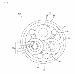
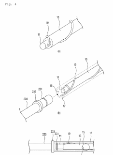
For example, the invention is related to the Electric vehicle charging cable, first we will draw the FIG. 1 showing the overview of the invention:

Exploded View Patent Drawings: Revealing Component Relationships
After establishing what your invention looks like from the outside, the next logical step is to show how it all comes together. An exploded view patent illustration reveals the internal architecture and component relationships that are crucial to understanding how your invention works. This view separates individual parts with space between them, allowing each component to be seen clearly while still showing their relative positions.
The exploded view serves multiple purposes in patent drawings. It clearly shows the assembly order, helping others understand how your invention is constructed. Each component receives its own reference number, creating a complete inventory of parts that will be referenced throughout your patent specification. In more complex assemblies, dotted lines might connect related parts to clarify their relationships.

Standard Engineering Views in Patent Drawings
With the overview and exploded views establishing the basic understanding of your invention, standard engineering views provide comprehensive documentation from every angle. These orthogonal patent illustrations include top, bottom, front, back, and side views, each showing the invention from a different perspective.
The top view shows your invention as seen from directly above, revealing the layout and arrangement of components on the horizontal plane. The bottom view, conversely, shows the invention from below, exposing structures that support or connect to other components. Front and back views provide direct sight lines to the invention’s primary faces, while side views complete the picture by showing the profile and depth.
Component-Level Patent Drawings for Critical Elements
After establishing the overall device and its component relationships, the next step is to focus on critical components individually. Component-level patent illustrations zoom in on specific parts of your invention that deserve special attention, either because they embody novel aspects of your invention or because they require detailed explanation.
Each component-level drawing typically focuses on one major component per figure, showing its construction in detail. These patent drawings reveal subcomponents and how they fit together, often including cross-sectional views that expose internal structures not visible from the outside. For particularly complex subassemblies, additional exploded views might be necessary.
Operational Sequence Patent Drawings: Showing Movement and Function
Many mechanical inventions involve movement or state changes during operation. For these inventions, operational sequence patent drawings complete the picture by showing how the device functions dynamically. These drawings show the invention in different operational positions or states, capturing the motion or transformation that occurs during use.
Multiple figures might illustrate a sequence of movement, with each figure representing a different stage in the operation. In some cases, phantom lines (dotted or dashed lines) show the range of motion a particular element might travel through. These sequence drawings are particularly important for mechanical patent applications where the functionality involves mechanical movement, transformation, or reconfiguration.

Software Patent Drawing Strategies: Visualizing the Intangible
Software inventions present unique challenges for patent illustrations. Unlike mechanical inventions with tangible components, software innovations involve processes, architectures, and data flows that must be visualized effectively. A thoughtful sequence of patent drawings can transform abstract software concepts into clear, comprehensible visual representations that strengthen your patent application.
System Context Diagrams for Software Patent Applications
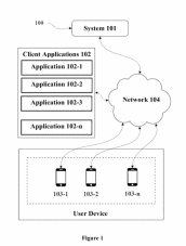
The journey of documenting a software invention begins with establishing its place in the world. A system context diagram provides this critical foundation in software patent drawings by showing how your software system interacts with its operational environment. This high-level diagram depicts your system as a central element surrounded by the various external entities it interfaces with.
When creating a system context diagram for your patent application, include all relevant external entities such as users, other computer systems, databases, or hardware devices that your system communicates with. The diagram should clearly illustrate the data flows between your system and these external entities using arrows that indicate the direction of information transfer. For example, our invention is related to the System and method for concealing information associated with a physical mail package.
System Architecture Patent Drawings for Software Inventions
Once the external context is established, the next step is to open the “black box” of your system and reveal its internal architecture. A system architecture patent drawing illustrates the major components or modules that constitute your software system and shows how they interact with each other to achieve the system’s purpose.
When developing an architecture diagram for software patent applications, identify the major functional components of your system, such as processing modules, data stores, interfaces, and service layers. Show how these components interact by illustrating the connections between them, indicating the direction of data flow or control. Each component and interface should be clearly labeled to explain its purpose within the system.

Patent Flowcharts: Essential for Software Process Documentation
While the architecture diagram shows the static structure of your system, patent flowcharts document its dynamic behavior. For each significant process in your software invention, create detailed flowcharts that show exactly how information flows through your system and how it’s transformed along the way.
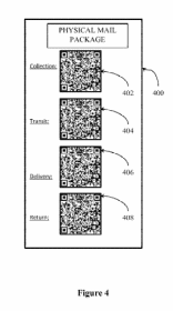
Effective software patent flowcharts include clear start and end points that define the boundaries of each process. Process steps are typically represented as rectangular boxes containing concise descriptions of the operations performed. Decision points, shown as diamond-shaped boxes, indicate where the process flow branches based on certain conditions. Arrows connect these elements to show the direction of flow through the process.
Patent flowcharts often form the core of your software patent drawings, as they directly illustrate the novel processes that may be claimed in your patent. They show the logical flow of your software’s operation in a way that text alone cannot effectively convey. Patent examiners frequently refer to these flowcharts when evaluating whether your claims are supported by your disclosure.

Data Structure Diagrams in Software Patent Applications
If your software invention involves novel ways of organizing or structuring data, include dedicated diagrams that illustrate these data structures. Data structure patent drawings show how information is organized, stored, and related within your system.
These patent illustrations might show the organization of data elements, such as classes or objects in an object-oriented system, tables in a database, or custom data structures like trees, graphs, or specialized arrays. Show relationships between data elements using appropriate notations that indicate inheritance, composition, association, or other relevant relationships.
User Interface Patent Drawings for Software Inventions
For software inventions that involve user interaction, user interface patent drawings complete the picture by showing how humans interface with your system. These diagrams illustrate screen layouts, control elements, and interaction flows that are essential to understanding how users engage with your software.
When creating user interface patent illustrations, show representative screen layouts that depict the arrangement of information and controls. Indicate interactive elements such as buttons, menus, input fields, and display areas. For complex interfaces or interaction patterns, consider creating multiple diagrams that illustrate the flow of user interaction through various screens or states of the interface.
Strategic Reference Numbering for Patent Drawings
Creating a logical, consistent numbering system for your patent drawings helps readers navigate between different figures and understand the relationships between components. A well-designed reference numbering scheme becomes particularly valuable in complex inventions with numerous parts or multiple embodiments.
Mechanical Patent Drawing Numbering Systems
For mechanical patent drawings, organizing your reference numbers in a hierarchical manner enhances clarity and reflects the structure of your invention. Begin by assigning a base number, such as 100 or 1000, to your main assembly or overall invention. This immediately signals to readers that they’re looking at the primary system rather than a subcomponent.
As you label individual components in your patent illustrations, maintain consistent increments between reference numbers. Using increments of 2, 5, or 10 between consecutive numbers leaves room for adding components later if needed without disrupting your numbering scheme. This foresight can prove invaluable during the patent prosecution process.
When dealing with subcomponents that belong to a larger part, extend your numbering scheme hierarchically in your patent drawings. For instance, if component 104 consists of several smaller parts, label these using decimal extensions (104.1, 104.2, 104.3) or alphabetical modifiers (104a, 104b, 104c). This approach instantly communicates the parent-child relationship between components.
Software Patent Drawing Numbering Conventions
Software inventions benefit from a slightly different numbering approach in patent drawings that reflects their functional organization rather than physical assembly. One effective strategy divides reference numbers into functional categories, with each category assigned a specific number range.
For instance, in your software patent illustrations, you might number system components or modules in the 100s range, process steps in the 200s range, data elements or structures in the 300s range, and user interface elements in the 400s range. This categorical approach immediately communicates the type of element being referenced, helping readers navigate complex software diagrams more effectively.
The systematic numbering of process steps deserves special attention in software patent drawings. When numbering steps in a flowchart, the sequence of numbers should follow the primary or most common flow path through the process. This makes it easier for readers to trace the normal execution sequence just by following ascending reference numbers.
Best Practices for Creating Effective Patent Drawings
Developing patent illustrations that effectively communicate your invention involves more than just following formal requirements. Several key practices contribute to creating drawings that strengthen your patent application and clearly convey your innovation.
Maintaining Consistency in Patent Drawing Style
Consistency forms the foundation of effective patent drawings. Use the same style, line weight, and numbering approach throughout your complete set of illustrations. Consistent representation helps readers develop a mental model of your invention as they progress through the figures. If multiple people work on your drawings, establish standards to ensure uniformity across all figures.
Prioritizing Clarity in Patent Illustrations
While artistic merit might be valued in other contexts, patent drawings should prioritize clarity over aesthetics. Your patent illustrations don’t need to be beautiful or artistic—they need to be clear and understandable. Clean lines, appropriate spacing, and judicious use of graphical elements all contribute to making your drawings easy to comprehend.
Finding the Right Level of Detail in Patent Drawings
Finding the right level of detail represents another crucial balance in patent illustrations. Include enough detail to enable someone skilled in your field to understand and implement your invention but avoid cluttering drawings with unnecessary elements that might distract from the essential aspects. When in doubt, create additional figures that focus on specific details rather than cramming too much information into a single drawing.
Depicting Multiple Embodiments in Patent Drawings
Many inventions can be implemented in multiple ways or configurations. If your invention includes alternative embodiments or variations, include separate patent drawings for each major variant. This comprehensive approach strengthens your patent by securing broader protection and demonstrating the flexibility of your innovation.
Using Shading Techniques in Patent Drawings
Shading can be a powerful tool for showing shape and form, particularly in mechanical patent drawings. However, use shading judiciously and according to patent office conventions. Excessive or improper shading can make reproduction difficult and might obscure important details. When used correctly, simple line shading can effectively communicate three-dimensional forms without compromising clarity.
Thorough Labeling in Patent Drawings
Thorough labeling completes your patent illustrations and connects them to your written specification. Every significant part should have a reference number, and every reference number should be explained in your specification. This comprehensive cross-referencing ensures that visual elements and textual descriptions work together to fully communicate your invention.
Conclusion: Maximizing Protection Through Strategic Patent Drawings
Well-executed patent drawings represent the intersection of art and science, combining visual clarity with technical precision to communicate your invention effectively. By following a systematic approach—starting with overview drawings and progressing to detailed components for mechanical inventions or beginning with system context and moving to detailed flowcharts for software inventions—you create a natural flow that helps patent examiners understand your innovation.
Patent drawings serve dual purposes that extend beyond mere illustration. On the legal side, they define the scope of your protection by visually representing the elements claimed in your patent. On the technical side, they provide the blueprint that enables others to understand how your invention works and establish that you’ve met the enablement requirement of patent law.
The time invested in creating comprehensive, clear patent illustrations yields returns throughout the patent process. Well-executed drawings can streamline examination by reducing examiner questions, strengthen your patent against potential challenges by clearly showing your invention’s novel aspects, and potentially save significant time and expense during prosecution.
While this guide provides a foundation for creating effective patent drawings, remember that patent offices in different jurisdictions may have specific requirements and conventions. Always consult the latest regulations for your target jurisdiction, or better yet, work with a qualified patent professional who can ensure your drawings meet all formal requirements while effectively communicating your invention.